





AN important aspect of the lathe, from the amateur’s point of view is that with the minimum of equipment it can be employed for light milling operations. Taper-shank end-mills can be mounted in the spindle, while parallel-shank mills and facing cutters can be held in a chuck. Using a stub mandrel in a chuck or a long mandrel with one end in the chuck and the other by the tailstock, various types of circular cutters can be run for sawing, slotting and similar operations. For very simple operations, the work can often be clamped to the top-slide and traversed past the cutter by cross-slide and longitudinal feeds. In some instances, the top-slide can be removed and an angle-plate substituted, thus providing a larger surface for mounting. The most versatile fitting, however, is a vertical slide which can be fitted in place of the top-slide. Given such a slide, the basic accuracy of the work produced on it will largely depend on the setting. Usually, the bases of slides are graduated to provide approximate settings, but these are not nearly accurate enough and should not be relied upon, except, perhaps, for very simple operations.
Setting Vertical Slides
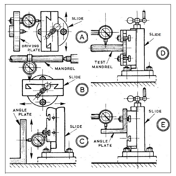
For more precise settings, involving normal parallel and right-angle faces, the face of the slide must be adjusted to correspond with the cross-slide or saddle feed. This can be done either with a round-ended pointer, or preferably with an indicator gauge to show errors in setting by the movement of its hand. Referring to diagram A, showing a plan view of a slide set at right-angles to the lathe axis, a round-ended pointer could be mounted on the driving plate, and the slide fed near to it. The gap between pointer end and the face of the slide should be equal across the face as the slide is fed, and may be checked by observation or using feeler gauges. If an indicator is mounted as shown, any error will be revealed as a variation in the reading of the indicator, and when the reading is steady the slide is correctly set. With either method, should an error be shown the slide must be suitably re-adjusted. Referring now to diagram B, where the slide has been turned through 90 deg., a round-ended pointer or indicator can be mounted on a mandrel, held one end in the chuck, the other supported by the tailstock, the other supported by the tailstock. Similar principles of setting are then employed in conjunction with saddle feed along the bed.
These two basic settings cover the majority of set-ups; and for adjusting work true on the slide, the same principles apply. Thus, should it be required for the edge of a component to run parallel with the lathe bed, the round-ended pointer or indicator is moved into a vertical attitude. With cross feed for diagram A, or saddle feed for diagram B, a level setting should then be obtained. If feed is to be from the vertical slide itself, the pointer or indicator should be set to the edge of the work, and the gap or reading should be uniform as the work is raised and lowered. In every case of inaccurate setting the work must be adjusted on the slide. In regard to accuracy of the slide itself, any error shown by the table against a fixed indicator when the vertical slide is operated would suggest an error in the table. This method, however, would not reveal an error in the guide ways of the slide. To do this, a test would have to be made, either on the lathe or a surface plate, against a true angle-plate, as at C, or using a test mandrel, as at D, machined between centers. An inaccurate slide can be packed at its base. The setting of an angle-plate can be checked as at E, with saddle and cross-slide feeds. Inaccuracy on the plate can be corrected by packing, and the other way by suitably adjusting, the plate on the slide table.
LONG types of screw of square-thread or Acme form, for use as leadcrews, feedscrews, jackscrews, and for many similar purposes, present problems of production which do not occur in shorter varieties of screwed components. With the latter, there is usually no problem of support when the work can be held in a chuck or mounted on the faceplate; and even if the tailstock has to be used, a tool set-up can generally be arranged without difficulty. It is otherwise with very long threads as, apart from anything else, the length demands use of the travelling steady close to the tool position to obviate spring and wobble with the work pushing away from the tool on a normal depth of cut, and digging in when the cut is increased.
Screwcutting Long Thteads
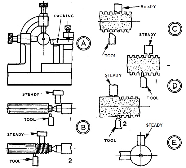
That is to say, as in ordinary turning, functions of the travelling steady are to keep the work turning truly, and to provide the rigid backing necessary to control depth of cut. On a long screw too, with the tailstock close up, a fairly considerable forward overhang of the tool may be necessary for the topslide to pass along by the tailstock for beginning the cut. Because of the rather heavy cut normal for broad threads, the tool would be subject to spring and chatter, unless supported with packing between it and the cross-slide table, as at A. Setting of the steady in relation to the tool can be important; and normally the two should not be directly opposite, as there is a good chance of swarf from the tool running round and getting between the work and the steady jaws which would have the immediate effect of greatly increasing the depth of cut and possibly breaking the tool. Hence the steady is usually somewhat before or behind the tool.
Of course, a position before the tool is not practicable if the thread diameter is less than that of any plain portion or boss further along, as there would be a shoulder obstructing the steady jaws before the tool arrived at the end of the thread. With the steady positioned behind the tool, the tailstock alone supports the work at the start of the cut, as at B1; then, after the first few turns, the steady comes into action, as at B2, providing support to the end of the cut. A number of cuts must be made to bring a square or Acme thread to depth, and after the first one the steady jaws are running on reduced support, touching only at the original diameter. With several cuts on long traverse, this can result in wear on the steady jaws, which become grooved from working always in the same relationship to the tool, as at C. It may be noticed by irregularities or difficulties in the cut, and by a “clicking” as the saddle is returned. On a one-off job, the effect may be slight and not occasion difficulty, though there are often points to watch.
Any alteration of the tool sideways, such as if it has to be removed and sharpened (which is best avoided, if possible, in the course of cutting a square-thread screw), may result in very thin edge support, as at D1, with impending variations in cut. If the steady runs before the tool, there will almost certainly be variations in cut with any type of grooving of the jaws. With the steady providing proper support, at position D2, there would be slack support on the thread; while firm support on the thread would give extra depth of cut at the position shown, with the possibility of tearing the work, or breaking the tool. Given that the tool cuts freely, many difficulties can be avoided by ensuring the steady jaws are true, and bed on the work to maximum curvature, as at E. This demands preliminary machining, and truing when necessary, with a fly-cutter bar of work radius, adjusting the jaws and traversing the saddle, as otherwise the flat ends of the jaws would wear ridged.
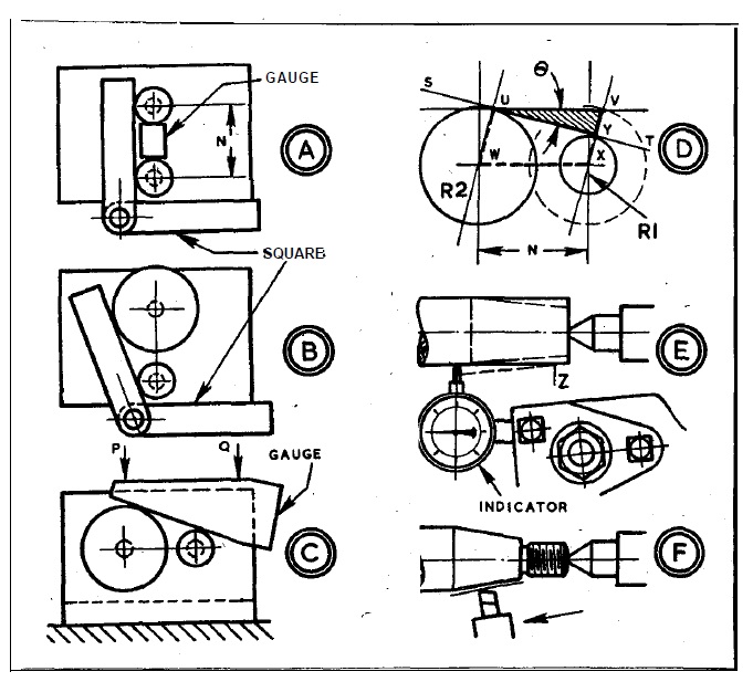
ACCURACY of a square can be checked by two discs of the same diameter fixed by screws to a piece of plate, and set so that the blade of the square touches both when the stock is applied to the edge of the plate. By turning the square over when the blade has touched the discs on side, so that it touches them the other side, accuracy of the square can be proved. By this method also, it is possible to set the two discs at right angles to the edge to which the stock of the square is presented as at A, where the square is an adjustable type, or clinograph. On this principle, using discs of different diameter, angles either side of the vertical can be obtained accurately, and an adjustable square set to them for laying out or checking work. The setting can be done at least as accurately as when using an expensive adjustable square with vernier and only micrometers are needed for turning the discs and making a gauge for spacing the first pair.
Accuracy For Angles and Tapers
Setting the Discs
The setting is done as at A. The discs are mounted vertically in the straight-edged plate by shanks threaded for nuts, which hold them securely. The shank of the one further from the edge is a close fit in its hole, and all other shanks are similarly well-fitting here. The shank of the setting truly by a square, and an end gauge is placed between the two discs for spacing accurately to distance N. The diameter of the discs can be to choice, as can the spacing; for many purposes the discs can be 1/2 in. dia., and their spacing 1 in.
Once the discs have been set and the one nearer the edge firmly fixed by the nut on its shank, the other can be removed and a larger substituted, as at B. The blade of the square can then be set to angle. Thus, with the plate having one accurately fixed disc, others can be used for obtaining required angles. For working on a surface plate, angles can be obtained in the same manner, as at C, where a small angle plate has been drilled to take discs. To mark off an angle gauge, plate material can be stood on the discs and clamped; and at the finish, an accurate check can be made with a surface gauge or indicator at points P and Q, which should be horizontal.
Using Trigonometry
Dimensions of discs can be found using trigonometrical tables. The sine is a decimal fraction, and tables may be to six figures with angles and degrees in minutes. With spacing of discs1 in., the fraction for each angle is an ordinary decimal fraction, and added to the radius of the smaller disc to obtain that of the larger. If the spacing exceeds 1 in., then the fraction is multiplied by the spacing. For 5 deg. for example, sine is 0.087156 which is added to the radius of the smaller disc; so one is 0.250 in. radius, and the other0.3371 in. radius. Proof is as at D. Here the spacing is N and the angle ?. Line S-T is the required angle, and is a tangent to the two discs. Line U-V is horizontal on to another large disc of the same size. This length is the same as W-X, or N. U, V, W, X form a parallelogram, and UYV a right-angled triangle, with VY/UV equaling the sine. With spacing N at 1 in., VY is the fraction taken from the tables.R1+VY=R2.
The principle may be adapted to set a lathe topslide accurately to angle for machining tapers on shafts. The slide is set approximately to angle, and the indicator mounted with its plunger at centre height and at right angles to the parallel work, as at E. Beginning with the indicator at Z and set to ?, moving the slide 1 in. should bring the reading to correspond to the fraction for the sine; and while they do not agree, the slide requires adjustment. To adjust a slide to a shaft already machined taper, an approximate setting should again be made, with the tool at centre height and brought fairly close to the shaft.
OF the different means for transmitting power between shafts, belts and pulleys are undoubtedly the simplest and within their application, possess virtues lacking in gears and chain and sprocket drives. With belt, shafts can be relatively distant, out of line in certain respects, or even at right angles. Flexibility and slip absorb shock, and with flat and round belts rotation can be reversed. No lubrication is required – although on large flat belts dressing is generally used to maintain flexibility and limit slip.
There are disadvantages, of course, by comparison with gears or chain and sprockets, chiefly in regard to slip. Gears in particular admit very large ratios or differences of speed between shafts in close proximity, whereas with a belt on very small and large pulleys severe slop would occur as a result of the reduced are of “ wrap round ” on the smaller pulley. Consequently, in the average short-centre belt drive it is wise to limit the pulley ratio to about 1 to 4 ( 1 in. and 4 in. pulleys ), though for light drives or if the “ wrap round ” is increased by jockey pulleys, the ratio can easily be increased to 1 to 10 or 12.
Different Type of Belt Drives

Diagrams A, B, C, D, show common belt and pulley sections. Flat belts of leather or canvas composition are employed on flat or slightly crowned pulleys, B, this feature causing the belt to centralize itself on the pulley and not run off as might be supposed. For light drives with flat belts of about 1 in. width, as in small workshops, leather is generally the best material and, after initial stretching, will run for long periods with little attention. Joints can be made by chamfering the ends and stitching with thin string or strong thread. To shorten, the stitches can be picked out, the end(s) rechamfered and restitched.
Standard Sections
Vee-belt, C, are of one-piece canvas and rubber construction, and provide the best form of simple drive. They are in a variety of sizes and lengths for industrial use and automobile dynamo and fan drives. No difficulty should be experienced in filling particular needs. Round belts, D, for light workshop drives are of leather about &in. dia. Joining can be chamfering the ends and stitching and binding though common metal fasteners consist of two sleeves, each threaded internally for the belt to “ screw ” in, and one sleeve having an eye, the other a hook, for joining.
Pulleys for such belts should be round section in the bottom, with flanges fairly deep and slightly flaring to keep the belt on; for this type has a propensity to run off the pulleys at times, particularly when using metal fasteners. An open belt drive is as E, and in small sizes either pulley can be the driving one. But in an industrial drive the left-hand pulley would be the driving one, the “ pull ” side of the belt at the bottom and the “ slack ” side at the top to provide increased “ wrap round ” and better drive on the pulleys. A crossed belt drive, providing reversed rotation, is as F, and either pulley can be the driving one.
Shafts should be parallel in plan, not as G, which would cause a flat belt to run off. In the case of vee-belts this condition tends to cause them to turn on their sides. A worn pulley, H, can spoil a flat belt by it mounting a flange ( old type Austin Seven fan pulley); the remedy is to recrown the pulley as I by machining in a lathe.
SUCCESS in producing good threads with a single-point tool (screw cutting in the lathe) depends on quite a number of factors on the condition of the lathe, the setting of the tool, the type of material, and, by no means least, the manner or sequence in which the cuts are taken.To obviate shake and endplay, the lathe spindle bearings and thrust must be in proper adjustment. Indentations of centred work should be clean and accurate, and sufficiently large for firm support and resistance to wear-on the tailstock centre, which should be constantly lubricated and from time to time checked for setting. The cross-slide should be adjusted to noticeable (but not heavy) friction against the feedscrew; while topslide friction should be fairly heavy to prevent inadvertent movement. Saddle and leadscrew must also be well adjusted.
Screw Cutting Tool Feeds
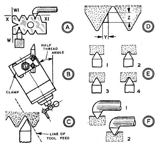
Using a gauge, as at A, tools can be checked as they are ground to shape and given clearance, and as they are afterwards set up. Holding edge W-WI to the face of a chuck or the work, an internal tool can be checked for setting; while an outside one can be verified in a similar manner by presenting edge X-XI to the work. Such a gauge has vees of 60, 55 and 47-1/2 deg., covering metric, US, Whitworth and BA threads. A single face at 14-1/2 deg. provides for checking and setting tools for Acme and standard worm threads.
Given that a thread is tine pitch and consequently shallow, no difficulty is likely to be encountered merely by taking a series of cuts with straight in-feeds, whatever the material. Again, should the material be brass, phosphorbronze, or cast iron, all of which chip or flake as they cut, or aluminium alloy which cuts easily, unusual difficulties are not likely unless the threads are coarse and deep. But any steel or tough material, even with threads of quite small or moderate pitch, will almost certainly give rise to difficulties-roughness, digging-in, stripping-owing to the converging flows of metal as the thread deepens.The remedy, of course, is to avoid this self-obstructing flow of swarf, by arranging for the tool to cut, wholly or at least substantially, on one edge at a time, when the swarf runs off as a single flowing ribbon, or in regularly twisting and breaking curls. That is the merit of a topslide setting at half the thread angle, as at B, when the tool is fed straight down one flank of the thread, as at C.
Such an arrangement, however, contains a number of drawbacks, and has no advantage over a regular sequence of nuts. The “generated” flank of the thread is rough and requires finishing by a backcut. With a whole-form tool, there is still a risk of a dig-in at times-obviated by using a relieved tool as shown. Tool overhang is fairly large, and a special clamp may be needed. The slide may obstruct either the chuck or the work, and double or multiple-start threads can be finished only at some risk of their being out of accurate phase. Depthing requires use also of the cross-slide.
A regular sequence of cuts is based on the principle at D. On one flank of the thread, a cut of equivalent depth can be obtained by a topslide feed Y, or a cross-slide feed Z. Thus, a cut Y will be on one flank, and the cut Z following will be of the same depth on that flank, and cutting also on the other flank at the bottom, bringing the tool into the full form of the thread. Proportions vary according to thread angle, and may be held from zero on the micrometer collars. Taking Z as 0.100 in., Y is 0.060 in. for metric and US threads; 0.052 in. for Whitworth; and 0.044 in. for BA. A first cut taken as E1, can be followed as E2 (Y), then as E3 (Z); and a back-cut E4 will give clearance and finish, for beginning again. The same is true for internal threads, as at F1 and 2.
WHEN the set-up of a cylinder casting or sleeve has been made in a chuck, or on a faceplate or angle plate jig the process of producing the bore for the piston consists first of machining our parallel and nearly to size. Then follows the finishing operation, which may be reaming, though lapping is often better and requires no expensive tools. The number of cuts necessary to rough out the bore and bring it nearly to size depends mainly on the amount of metal to remove and the type of lathe and tool employed. Where considerable metal is present and the lathe is small, numerous cuts are required; and where the bore of the casting is small in relation to length, springiness in the tool will slow the operation and call for extra cuts, even on a lathe of adequate power .
Finishing Small Cylinders
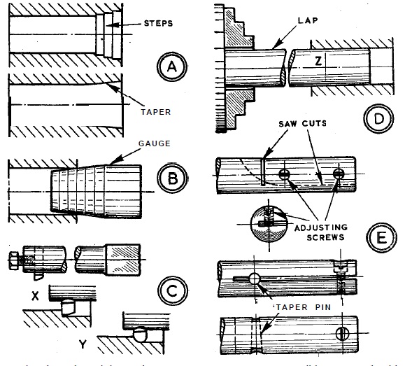
On early cuts, finish left in the bore is of little importance so long as parallelism obtains and there are no chatter marks. So far as possible, each cut should be taken completely through; if the tool wears or goes off cut for any reason, a start after re-sharpening should be made on the same cut, or on one a very little deeper. This principle may have to be modified if there should be a hard spot or low part which destroys the tool edge. Then a deeper cut to get under the hard area may be essential. But as soon as possible a return should be made to the principle of taking cuts right through. A series of steps or partial cuts, as at A, should be avoided, particularly as the bore is nearing size. Otherwise the tool may spring and the surface of the bore acquires a glaze, which will result in taper or bell-mouthing. Rotational speed should be low on early or deep cuts, and may be increased on later light cuts, subject to running without chatter. In the absence of slow feed, the whole operation may have to be performed by hand feed, attempting to achieve continuous motion without pauses – which could result in rings in the bore or a tendency towards chatter.
Careful use of inside calipers at different positions in the bore, as soon as the rough surface has been removed, will reveal parallelism. If not, adjustments must be made to the lathe, followed by further tests cuts and checking. Final cuts should leave a finish which feels smooth and looks bright without being polished. Cast iron can be machined dry, and swarf kept blown out, while broze or steel require coolant with lubricating properties and ensure that swarf does not curl round the holder. A taper gauge, as at B, can be used for checking size, reference marks or rings being made between the two diameters. With a smooth tooled surface, a dimension of 0.001 in. on the diameter is ample to leave for finishing. A suitable tool holder, as at C, can be turned from square steel and the tool held in a cross-wise hole by a setscrew. A tool with a square edge and small round tip, as at X, has the minimum tendency to chatter, as against the maximum tendency of a tool, as at Y, with a large radius.
The lap for finishing can be of aluminum alloy, as at D, turned (and titled) for the cylinder just to go on, there being a slow taper from the end to Z. Fine valve grinding paste should be smeared evenly over the lap and the cylinder tried each end (held in the hand), the lathe pulled round by hand or running slowly. The top diameter of the lap may have to be eased for the cylinder to go right on. At the finish of lapping, the lap and cylinder should be scrubbed, followed by application of metal polish, then paraffin and lubricating oil, to work abrasive out of the metal. Adjustable laps, as at E, can be made by slotting round material and fitting grub screws, or a taper pin and a screw.
