





THERE are times when even the simplest operation would be greatly facilitated if one had a third hand. In some instances, of course, work cannot proceed unless assistance is available or means are devised to enable one to work single handed. This is especially pertinent when long or weighty material has to be mounted with one end in the vice, or a pedestal or bench drilling machine is employed for parts which are extensive or overhanging. Ordinarily, gripping material in the vice presents no problem. It can be held with one hand while the vice is tightened with the other. If it is heavy but short and needs to be mounted centrally at a certain height out of the vice jaws, a piece of wood or similar packing can be laid in the jaws on the slide and the material rested on this while the vice is tightened.
Again, should such a piece of material be no longer than a comfortable arm’s reach, one can still hold the distant end and operate the vice handle oneself. Beyond this length, however, the distant end must be supported in some manner. Nor is it a question only of initial mounting, for often the support must be maintained. A piece of heavy steel bar, for example, will twist in the vice and descend when let go or if extremely heavy pressure is applied the vice may be unnecessarily stained-and lighter material, like a board, may have to be gripped so hard that the vice jaws leave marks. In a low building it is generally convenient to support from the roof via a cord or piece of light chain. To find the spot where the support needs to be, the material is placed one end in the vice jaws, the other on the floor, then a plumb-line (a weight on a string) carried up from the floor to the roof where a placed in a nearby rafter. If cord is used it should be tied to a wire ring or loop in which the material rests as cord alone grips the material, which then proves more difficult to move along. If chain is used it can be looped round the material and a bolt passed through the links-which also affords a means of height adjustment. Should the support line came between rafters a member can be fixed across them, when, if desired, a number of hooks can be fitted, A.
Supporting and Steadying
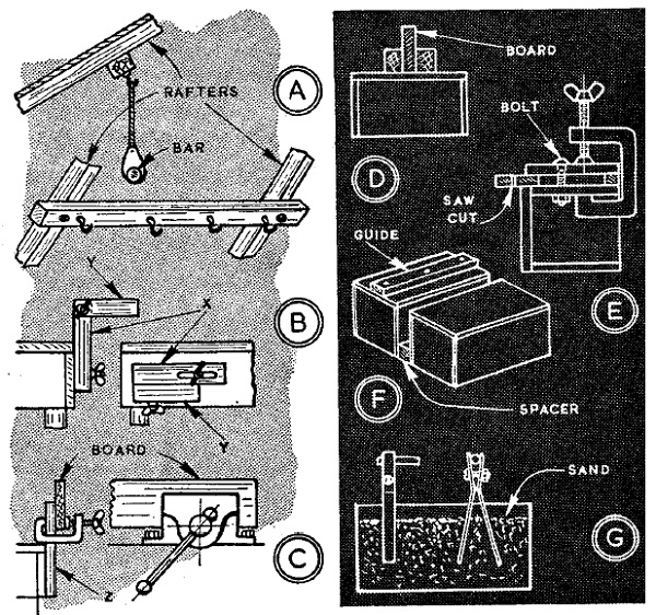
Brackets or supports attached to the bench are other means of maintaining the distant end material level with vice jaws. The type at B is compact, adjustable, folds down to the bench when not in use and may be constructed either from light angle iron or wood about 1-1/2 in. square. Part x swings up and may be slotted to set for height while part y turns out horizontally. Fixing can be by bolts and wing nuts. Support for the distant end of a board when planning the edge may be provided, C, by attaching a strip of wood , z, vertically to the front of the bench, then gripping the board with a clamp. Should such a mounting be impracticable, however, alternative means of mountmg are inverted boxes on the floor with pieces of square or simiiar wood nailed or screwed to the bottom. These form a channel in which the board can be placed vertically, D. Endwise movement of the board, under plane pressure, is prevented by a cross-block at the end of the channel. Boxes also provide support when strip sawing or splitting boards. For a narrow strip, clamping to the side of a box is convenient, E, when a bolt may be used instead of a clamp. For cutting down a length two boxes may be spaced, F, one has a nailed-on guide to align the board while the saw, passing down the marked line, is kept central between the boxes. Support of a different nature to hold small parts in alignment for soldering, brazing, etc., may be provided as G. The parts may be laid or clipped on strip metal supports and these pressed into sand in a box or held while sand is packed round them-a method avoiding strain.
BASICALLY, a drilling jig is intended to guide the drill to the required point on the work, without the need for marking off or centre-punching, and to maintain the drill in alignment while the hole is produced-thus saving time and promoting accuracy. There are cases, too, where a guide for a drill is essential, even for one hole, such as when there are variations in the texture of the material, or the drill cannot be started squarely. These occur when drilling wood on the side of a knot, or starting a drill in metal on an uneven or sloping surface.
For general use, jigs can be in mild-steel, thick enough to guide the drill by the diameter when the point engages the work. The hole(s), should be centre punched, drilled undersize, then opened out with the drill(s) of the size to be used. The jig at A is used for spacing holes along the edges of metal or wood, for rivets or screws. It has the outer edge. In use, the first hole is drilled, holding or clamping the jig; then it is moved along, a hole at a time, and a rivet or screw used for spacing location.The jig at B is used when drilling out a broken stud-car cylinder head, manifold, or a similar component. The hole centres are carefully spaced, one drilled for an adjacent stud, and the other for the drill left undersize. A centre line intersects the centres of the holes and is carried to the edge to be aligned to a mark scribed on the work. The jig is clamped with a distance piece and nut. After a test start, the jig is removed, the indentation examined, and the jig replaced (readjusted, if necessary) to drill through the stud.
Simple Drilling Jigs
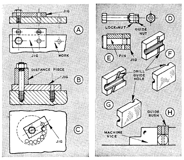
The jig at C is used when drilling a circle of holes to cut out a large round hole in sheet material. It is clamped for each hole and finally the centre piece is snipped or chiseled out and the edges smoothed with a file. This jig maintains accuracy, reduces subsequent work, and is useful where there are ribs or hollows which would cause the drill to run. When bolts have to be drilled for spilt pins, a nut can have a corner filed and the guide hole drilled. This guide nut is held in a vice each bolt to be drilled fitted with a lock-nut, screwed into the nut and locked for drilling, as at D. If orientation of hexagon on bolt and split pm hole is not important, a distance piece can be used on the bolt instead of a lock-nut.When pins have to be drilled for split pins, a small metal block can be drilled to accept them, and have the drill guide hole at the required distance from the end, as at E.
Split jigs, F and G, are easily made from round material. Two blocks, each provided with a small vee-groove (triangular file) are clamped with the vees aligned, then drilled for the pin, etc. The blocks are separated, small vee grooves are made where the guide hole is to be, the blocks then aligned with round material, clamped, and the guide hole drilled. If necessary, the block can be filed on their faces to grip the diameter held (and the drill hole opened out) for the assembly to be mounted firmly in a vice. Such jigs are valuable for angular holes G, as the angle can be accurately marked on the faces for filing the initial guide vees. When circular guide bushes can be machined and drilled (in a lathe), a machine vice mounting can be effected, as at H, with the bush above round material of similar diameter
FOR light flat belt drives, as may be used in small workshops, commercial types of fastener are usually too large and heavy, fitting badly on the curvature of small pulleys and tending to weaken the belts at positions where they are joined. Generally, better results are obtained-particularly with leather belts-by employing a chamfered and stitched joint or a type of small hinge which can be made to suit any width of belt. If time permits, much of the initial stretch can be taken out of a leather belt by attaching to a beam and hanging a weight on the end for several days. If height is wanting or the belt is long it can pass over the beam, packed to avoid sharp edges, and support a pair of weights. The belt being ready to be joined, pulley adjustment should be let right back and the belt wrapped round and cut so that when joined it will run slightly tight. It is a good plan to lap the belt before cutting, particularly if the pulleys are at fixed centres, placing a small piece of steel plate each side and gripping the joint with self-locking pliers. This should be done in the middle of a run with the tension checked, adjusting as required. Two marks, one each side of the joint at a measured distance, then provide means of verifying the length when the belt is removed to make the joint.
How To Belt Fasteners
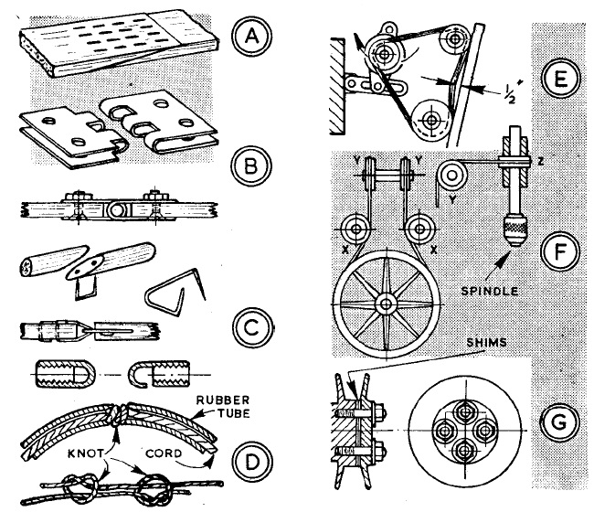
For the type of joint at A, chamfering can be done with a sharp knife, the faces coated with leather adhesive and the joint squeezed in the vice. When adhering it can be stitched with strong thread, lightly scoring the leather with a knife for the stitches to lie flush. For most small belts a hinged fastener, B, is strongly recommended. Construction is by folding sheet steel over a piece of metal slightly thinner than the belt. Gripped in the vice each piece is filed to make lugs fitting into those of the other. Held by pliers hinge pieces and metal are drilled right through and deeply countersunk on the underside-for screw heads to lie flush. Each piece is fitted with two screws, shallow nuts on the outside, and the screws lightly riveted. A piece of round rod, burred each end, makes the hinge pin. One advantage of such a fastener is the belt can be shortened by as little as 1/2 in. A round belt may be joined by butting its ends and driving a type of small staple through. Alternatively, the ends may be chamfered, C(top), coated with adhesive, a staple fitted and the joint bound with thread.
Again, two staples with long legs can be passed through the belt and turned, C(centre.) The end of each staple projects as an eye and the second is fitted linked into the first.
ALMOST all metals commonly found in workshops-iron, mild steel, cast iron, brass, copper-can be cut easily by hand if the correct saw is used. The exceptions are steels which have been hardened and tempered for special purposes. The metal saw differs from the wood saw in that it employs separate blades which have been special hardened and tempered for metal cutting. Because of this, the blades cannot be sharpened with files like wood saws, so when worn out they must be renewed. As they are hard, or semi-hard, they are liable to crack or break if twisted or wrung excessively.
Tubular Frames For Rigidity
Frames to take metal saws, or hacksaws as they are known, are made in a variety of sizes and designs for blades 9 in., 10 in. long. The standard non-adjustable frame takes blades of one length, but there are adjustable models of similar design which take all lengths of blade. Tubular frames are, in general, more rigid than those of flat section. For many purposes, the depth of cut with a hacksaw is limited by the depth of the frame i.e., the distance from the blade to the back of the frame. Special frames are available for exceptional depths of cut, however; these are called girder frames. A light frame, known as a junior, and formed from solid rod takes short fine toothed blades.
Under No Tension
A pad handle is made to take a standard hacksaw blade? Or portion of blade, the projection bemg adjustable. This has the advantage that it can be entered in awkward places where a standard or junior frame would be obstructed, and can also be used for cutting down wide sheets of used for cutting down wide sheets of metal. As the blade is not held in tension, more care is necessary when using the pad handle. Standard hacksaw blades have teeth of 14, 18, 24 and 32 pitch. This term”pitch” means the number of teeth in 1 in. Blades with the smaller number of teeth are called coarse pitch, and those with the greater numbers of teeth are of fine pitch. Pitches of 18 and 24 are commonly used for general work; 14 pitch can be used if the metal is very thick; 32 pitch can be used for sheet metal or thin-walled tubing. Junior blades are 6 in. long of 32 pitch, and have a pin at each end for mounting in the frame. Circular blades have a spiral tooth, and these are mounted in a standard hacksaw frame employing clips. These enable one to cut as with a fretsaw but in metal.
There are other types of saws and frames for particular purposes. Saws which are parallel in vertical section and without any set on the teeth are slitting saws; these produce a straight smooth-sided cut, but should not be used for general sawing. Hacksaws, junior saws, and similar blades, have a set on the teeth which provides clearance in the cut.
Choosing the blades. When choosing a blade for a particular job remember a coarse pitch of tooth for large sections and soft metals such as aluminum; and a fine pitch for harder metals such as cast steel or silver steel, and for thin sheet metal and thin-walled tubing. Shorter blades will serve the same purpose as long ones in many cases and are more economical. Long blades are better if the section of metal is large. The blade should lie snugly against the side of its attachments, with the pins firmly in the holes, and should be put in tension so as not to whip or bend when in use; the blade should remain firm and straight and should not be over-tensioned. For making long cuts down the side of sheets, the blade can be mounted at right-angles to the frame, by turing the fittings through 90 degrees before mounting the blade.
How To Use Saw
How To Make a Cut
A cut should be started with short, strokes, guiding the blade with thumb or finger. When a start has been made, the strokes should be long and firm using the full length of the blade.
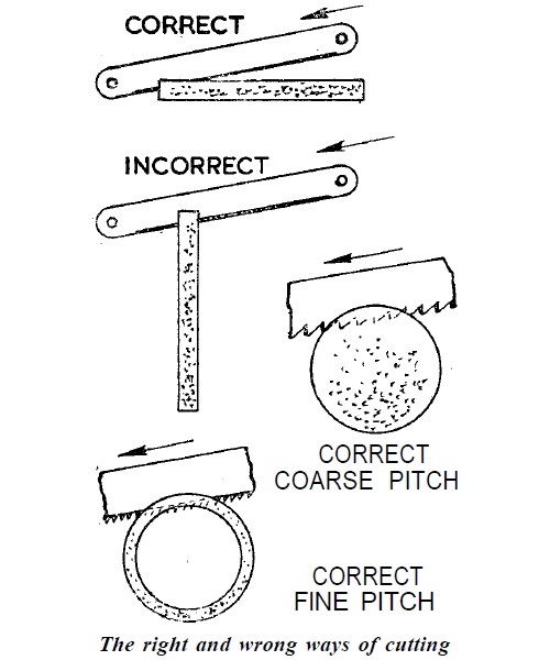
This method ensures that all the teeth are equally worn and therefore a smooth cut will result. If only the middle of the blade is used for a long time, when the ends of the blade are brought into use they tend to “seize”. This is due to the set not being worn. For this reason a new blade should not follow in the cut made by an old blade. Cutting metals is a matter of knowledge rather than knack and the correct and incorrect of cutting are illustrated.
AN important aspect of the lathe, from the amateur’s point of view is that with the minimum of equipment it can be employed for light milling operations. Taper-shank end-mills can be mounted in the spindle, while parallel-shank mills and facing cutters can be held in a chuck. Using a stub mandrel in a chuck or a long mandrel with one end in the chuck and the other by the tailstock, various types of circular cutters can be run for sawing, slotting and similar operations. For very simple operations, the work can often be clamped to the top-slide and traversed past the cutter by cross-slide and longitudinal feeds. In some instances, the top-slide can be removed and an angle-plate substituted, thus providing a larger surface for mounting. The most versatile fitting, however, is a vertical slide which can be fitted in place of the top-slide. Given such a slide, the basic accuracy of the work produced on it will largely depend on the setting. Usually, the bases of slides are graduated to provide approximate settings, but these are not nearly accurate enough and should not be relied upon, except, perhaps, for very simple operations.
Setting Vertical Slides
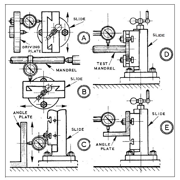
For more precise settings, involving normal parallel and right-angle faces, the face of the slide must be adjusted to correspond with the cross-slide or saddle feed. This can be done either with a round-ended pointer, or preferably with an indicator gauge to show errors in setting by the movement of its hand. Referring to diagram A, showing a plan view of a slide set at right-angles to the lathe axis, a round-ended pointer could be mounted on the driving plate, and the slide fed near to it. The gap between pointer end and the face of the slide should be equal across the face as the slide is fed, and may be checked by observation or using feeler gauges. If an indicator is mounted as shown, any error will be revealed as a variation in the reading of the indicator, and when the reading is steady the slide is correctly set. With either method, should an error be shown the slide must be suitably re-adjusted. Referring now to diagram B, where the slide has been turned through 90 deg., a round-ended pointer or indicator can be mounted on a mandrel, held one end in the chuck, the other supported by the tailstock, the other supported by the tailstock. Similar principles of setting are then employed in conjunction with saddle feed along the bed.
These two basic settings cover the majority of set-ups; and for adjusting work true on the slide, the same principles apply. Thus, should it be required for the edge of a component to run parallel with the lathe bed, the round-ended pointer or indicator is moved into a vertical attitude. With cross feed for diagram A, or saddle feed for diagram B, a level setting should then be obtained. If feed is to be from the vertical slide itself, the pointer or indicator should be set to the edge of the work, and the gap or reading should be uniform as the work is raised and lowered. In every case of inaccurate setting the work must be adjusted on the slide. In regard to accuracy of the slide itself, any error shown by the table against a fixed indicator when the vertical slide is operated would suggest an error in the table. This method, however, would not reveal an error in the guide ways of the slide. To do this, a test would have to be made, either on the lathe or a surface plate, against a true angle-plate, as at C, or using a test mandrel, as at D, machined between centers. An inaccurate slide can be packed at its base. The setting of an angle-plate can be checked as at E, with saddle and cross-slide feeds. Inaccuracy on the plate can be corrected by packing, and the other way by suitably adjusting, the plate on the slide table.
LONG types of screw of square-thread or Acme form, for use as leadcrews, feedscrews, jackscrews, and for many similar purposes, present problems of production which do not occur in shorter varieties of screwed components. With the latter, there is usually no problem of support when the work can be held in a chuck or mounted on the faceplate; and even if the tailstock has to be used, a tool set-up can generally be arranged without difficulty. It is otherwise with very long threads as, apart from anything else, the length demands use of the travelling steady close to the tool position to obviate spring and wobble with the work pushing away from the tool on a normal depth of cut, and digging in when the cut is increased.
Screwcutting Long Thteads
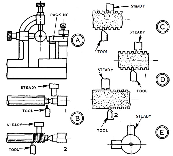
That is to say, as in ordinary turning, functions of the travelling steady are to keep the work turning truly, and to provide the rigid backing necessary to control depth of cut. On a long screw too, with the tailstock close up, a fairly considerable forward overhang of the tool may be necessary for the topslide to pass along by the tailstock for beginning the cut. Because of the rather heavy cut normal for broad threads, the tool would be subject to spring and chatter, unless supported with packing between it and the cross-slide table, as at A. Setting of the steady in relation to the tool can be important; and normally the two should not be directly opposite, as there is a good chance of swarf from the tool running round and getting between the work and the steady jaws which would have the immediate effect of greatly increasing the depth of cut and possibly breaking the tool. Hence the steady is usually somewhat before or behind the tool.
Of course, a position before the tool is not practicable if the thread diameter is less than that of any plain portion or boss further along, as there would be a shoulder obstructing the steady jaws before the tool arrived at the end of the thread. With the steady positioned behind the tool, the tailstock alone supports the work at the start of the cut, as at B1; then, after the first few turns, the steady comes into action, as at B2, providing support to the end of the cut. A number of cuts must be made to bring a square or Acme thread to depth, and after the first one the steady jaws are running on reduced support, touching only at the original diameter. With several cuts on long traverse, this can result in wear on the steady jaws, which become grooved from working always in the same relationship to the tool, as at C. It may be noticed by irregularities or difficulties in the cut, and by a “clicking” as the saddle is returned. On a one-off job, the effect may be slight and not occasion difficulty, though there are often points to watch.
Any alteration of the tool sideways, such as if it has to be removed and sharpened (which is best avoided, if possible, in the course of cutting a square-thread screw), may result in very thin edge support, as at D1, with impending variations in cut. If the steady runs before the tool, there will almost certainly be variations in cut with any type of grooving of the jaws. With the steady providing proper support, at position D2, there would be slack support on the thread; while firm support on the thread would give extra depth of cut at the position shown, with the possibility of tearing the work, or breaking the tool. Given that the tool cuts freely, many difficulties can be avoided by ensuring the steady jaws are true, and bed on the work to maximum curvature, as at E. This demands preliminary machining, and truing when necessary, with a fly-cutter bar of work radius, adjusting the jaws and traversing the saddle, as otherwise the flat ends of the jaws would wear ridged.
