





AS common fixing devices, screws are often taken for granted. Vet on their correct choice and fitting depend the good appearance and soundness of construction of work in which they are used. As is well known, they are of various sorts, shapes and size, those illustrated being the most frequently used. The woodscrew A may be in steel or brass, with a countersunk, round, or cheese head, or with a raised head, partly countersunk, partly round – often used in fixing interior panels and fittings in cars, when the head is chromium plated. The countersink angle is 90 degrees. Large screws with square spanner-heads are screw bolts, or coach screws; dowel screws have a thread each end and no head. The self-tapping screw B is in hardened steel, and can only be shortened by grinding. It may be provided with a countersunk, round, or sun head-partly rounded. This screw is used for fixing sheet metal panels. The outer panel (or part) is drilled clearance for the screw, and the interior panel drilled the core diameter. The screw is then forced through, cuts its own thread and pulls tight. It is often used for minor fittings in motor bodies. In other than sheet metal, it can only be driven a limited distances.
How To Fit Screws
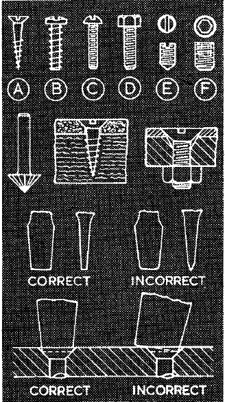
The ordinary metal screw C has a thread like a bolt, and a countersunk, round, or cheese head. It can be in steel or brass. When provided with a hexagon head D, it is a set-screw or sometimes a set-pin. Its uses are widespread. The grub-screw E has a 120-deg. pointed end and a screwdriver slot. It is commonly used for fixing collars, uullevs and small wheels to shafts, the bosses being drilled and tapped to take it. It has the most neat appearance when just flush with the boss.The headless socket screw F has a hexagon socket to take a key or spanner to tighten it. It is used much like a grub-screw, but can be obtained with a variety of ends-pointed, oval, hollow, flat, and with a small plain portion, when it is termed a dog point. It is in hardened steel.
Choosing the Screw
The choice of screws is narrowed by the materials being fixed, their thickness, and where the screws will be placed. Woodscrews can only be used on occasion in these materials and in sheet metal. Metal screws and setscrews can be employed in tapped holes, or in clearance holes, and for wood, etc., when nuts and washers are fitted. The length of screw is often governed by the thickness of materials – a woodscrew, for example, should not penetrate a panel for the point to emerge. Similarly, the size is frequently governed by the thickness of the material into which a screw enters edgewise, both from the point of view of splitting the material, and to obviate the head of the screw over: lapping the edge. In the case of grub-screws, they should be large enough to secure the pulley or collar firmly, but not so large as to distort or split the boss.
Countersinking
Two countersinking drills (or rose bits) are required, one for metal, one for wood. The one for wood will not cut metal, and the metal one may chatter in wood. Drills with only two flutes may be used with discretion in metal, when the angle has been altered. Before countersinking a clearance hole should be drilled, then the countersink run in so the head of the screw will just lie flush-for which operation care is required to produce neat, uniform work. The continuing hole for a woodscrew may then be made with a bradawl, if the screw is small. If lame, a core drill should be run in. this is important for hardwoods in which screws can be wrung off in fitting-particularly brass. In larger sizes, woodscrews are smeared with grease when fitting to enter and remove easier. When a metal panel is being fixed with countersunk screws, a countersink with a more acute angle can be used on occasion; the screw head will then bite on and hold the panel more firmly. An altered drill can be used for this type of countersinking.
Correct Screwdriver
The width of the blade of the screwdriver should be almost the diameter of the screw head, and its thickness so as just to enter the slot in the screw. The blade should be square and flat, not rounded at the ends, or sharpened like a chisel. A blade which is too narrow will damage the screw head, while one which is too wide will not drive the screw properly, and will score the surrounding surface.
Preventing Nuts Unscrewing
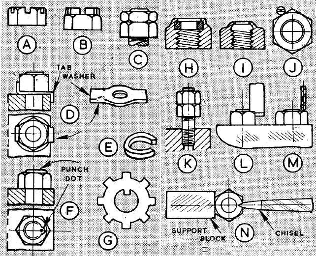
The problem of preventing nuts and threads slackening from vibration or other movement has been solved in various ways according to the requirements of assemblies, and, as usual, there are the “ do’s ” and “ don’ts.” Where rotation is in a particular direction, threads can be right or left-hand so there is a tendency for them to tighten. Spindles of cycle pedals, wheel hub nuts of cars and on occasion the actual wheel nuts of lorries are examples of this method and there are numerous other applications. Naturally care must be taken in dismantling to turn in the required direction. Split pins are perhaps the most common locking devices for nuts, whether on studs or bolts, and require the nuts to be either slotted or castle type, A and B. The slotted nut A needs less room where space is lacking, but is not so strong as the castle nut B with its circular portion on top in corporation the slots. Consequently, slotted nuts must not be substituted for castle nuts in important fittings. Split pins should fit the holes reasonably tightly, their heads be tapped into slots, then the legs opened round the ends of the bolts. Where there is continuous vibration (car big-end bearings), loose split pins will eventually wear so the legs break off and the pins fall out.
The Lock-nut
Another common device is the lock-nut C on U-bolts of car springs. Usually, the thin nut is on the end or outside, though in this position some engineers declare it takes the load on the bolt, owing to slight slackness in the threads of the thicker standard nut. Plain washers do not prevent unscrewing, but they are used in preference to others where firm pressure is required and it is desired to avoid scoring a metal surface by the underside of nuts. There are two types of tab washer, however, to provide security the single type D and the multiple type fitting on two or more bolts or studs, with a tab at each position to turn up on the nut.
In final tightening of nuts, care is required on multiple tab washers not to twist them, and on single tabs not to turn them into a wrong attitude for locking.
Spring Washer Types
In general use, three types of spring washer provide security: single coil E, double coil (similar) and the serrated type with bore or outside cut. Spring washers should not be used where loads are heavy, or the undersurface can be scored from dismantling. Under pressure, a single coil washer will often break or splay; a double coil, splay, and a serrated type break. Coarse, sharp single coil washers can be much improved by slightly straightening-in the vice, using pliers. Unless assemble is permanent, studs or bolts should not be burred. However, the centre punch dot F is often used on aircraft sub-assemblies. For removal, the displaced portion is chiseled or filed off. The multiple-tab washer G is used with keyed or splined shafts (car hub nuts). For unscrewing, the outside tabs must be fully released or the inner one will be sheared. Nuts fitted with a fibre insert H provide security against unscrewing for two or three removals – after which they are not so secure. They should not be used where heat can dry or burn the fibre. All steel nuts Z have an undersize piece at the end which grips the thread on the bolt or stud. These are a modem alternative for castle nuts on car big-end bolts. They avoid the difficulty of the split pin holes not being in line when the nuts are fully tight to overcome which, castle nuts have to be removed and filed on the bottom. In many fittings, a normal nut can be held by a small screw against a flat J – motorcycle crankpins. Studs can be fitted and removed by means of two nuts locked firmly together K – turning on the top one for fitting, on the bottom one for removing. Immovable nuts may be split L with a sharp chisel down one of the flats, or a small drill down one of the comers M – then a chisel used for splitting. Alternatively, a chisel and support block can be used as N.
THE ductility of most metals and alloys is one of their most useful characteristics, enabling many operations to be performed that would otherwise be impossible. For without stretch and flow in metals there would be no simple operations like riveting and bending, nor manufacturing processes such as rolling, wiredrawing, forging, panel-beating. Equally, however, there are occasions when it is undesirable for metals to change their shape, if no more than because subsequent rectification will be necessary; and with recognition of such cases a considerable amount of trouble and wasted effort may be avoided. Common processes where pressure is (inadvertently) put on the metal are shearing and chiseling. Thus, in cutting a strip from a piece of sheet, as at A, using shears, there is always a tendency for the strip to bend, because of the wedging action of the blades B (left). This is in addition to the curling which occurs. In chiseling, a similar wedging action is involved, B (right), when the sheet is laid flat on a metal block for cutting. Again, the strip is bent, though this time without curling. Tapping down the ragged edges can also stretch the metal along the cut edge, increasing the curvature; and this operation on the edge of the sheet may render it wavy or unstable. From this it will be seen that, to minimize the effects, shears and chisels should be sharp, and chisels slender at the end. To maintain metal in really good shape, however, it should be sawn, if necessary gripping or clamping thin sections between wood with the strip projecting, using a blade with fine pitch teeth, and slanting it so that they cannot dig in.
How To Do Metal Working
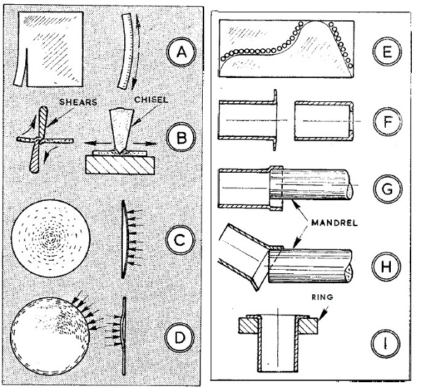
Even with sawing, bending sometimes occurs on strips cut from rolled bar sections, due to release of internal strains; the writer once had this occur with material for the rack of a small lathe. Usually, it is effective for mild steel to heat the bar red and cool out slowly, relieving the strains. Hammering metal on a surface results in thinning and stretching, which can be helpful or the reverse. When a strip or bar is bent, it is helpful to hammer along the edge of smallest curvature to straighten it by stretching, and usually this is preferable to attempting straightening in the vice by pulling – which in many instances introduces a reverse bend or kink. Hammering can cause difficulty with sheet metal through either of two effects. Taking a disc as an example, hammering and stretching in the central area C initially produces an “oil can bottom”, when if the perimeter is held the centre can be pushed one way and the other. Hammering the edge, however, particularly if not all round, renders this unstable, D, and laying the disc on a flat surface shows the edge to be upstanding in places. Pushing these down causes spring-up in other places. Rectification to flatten the disc consists for the domed centre C, of hammering the edge with diminishing blows to the centre, and for the unstable edge D of hammering the central zone, though experience must guide as to weight and location of blows. When sawing is impracticable, drilling round a perimeter is best, E, then the metal between the holes can be safely cut with a chisel, and the edge file-finished, avoiding hammering.
Flanging a tube is an instance of extremes required in metal working, F. For an outer flange, stretching to the larger diameter is necessary, and for an inner flange the metal must be compressed. The latter is the more difficult since ruckling tends to occur and only a small flange is practicable. The diameter of a tube can be increased by hammering round on a mandrel G, and a flare produced by inclining the tube and hammering round, H. This should also be done in producing an outer flange, for the metal must stretch gradually, otherwise splits appear. Final flanging can be done in a ring, I, but only when the flange has been initially well formed. Naturally, the need for annealing should not be overlooked, as hardening occurs with hammering.
THE most widely used precision instrument in 0 to 1 in. and 1 in. to 2 in. sizes is undoubtedly the standard outside micrometer. Most owner of small workshops, amateurs and others, apart from professional workers, acquire one or two according to their needs, and thus have an accepted standard of accuracy always read to hand. With care, too, a good micrometer remains acceptably accurate for a lengthy period; and by various methods and adaptations, its normal functions of measuring outside diameters and flat surfaces, can be greatly extended. It can be used, for example, to set spring calipers, telescopic and ball gauges, for checking bores of various sizes. It will similarly verify end gauges, thickness and slot gauges, distance pieces and stops, as they are being made or set. Again, it can be used to check depths of different types of keyways, widths of threads and splines, and similar items.
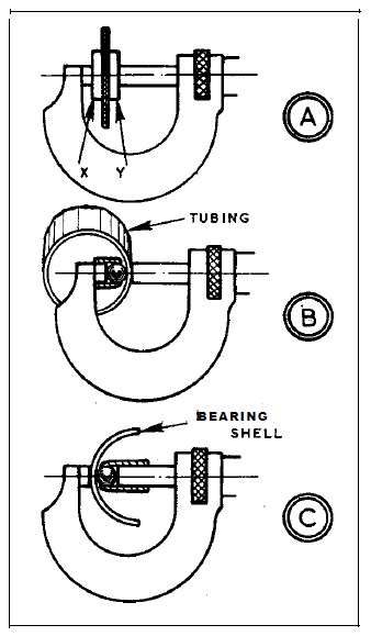
This versatility is of particular value to the small workshop owner or amateur, for the standard micrometer can thus be made to perform many functions which would otherwise demand special micrometers. The standard instrument with flat-ended anvil and spindle about 1/4 in. dia. cannot very well be used as it is on soft and flexible materials, for the measuring surfaces sink in and a false reading results. So for such materials, a special micrometer has enlarged contact faces. But by using as at A, two pieces of plate, x-y, soft material between them can be accurately measured with the standard micrometer – with allowance, of course, for the thickness of the plate.
Methods Of Adapting A Micrometer
This method is recommended for checking anything of an abrasive nature, such as a grinding wheel being dressed to given width and advisedly before checking any component surfaces should be carefully wiped, particularly if the component is being ground or lapped, or has been near abrasive. Micrometers for checking the wall thickness of tubes or other curved surfaces have ball-ended anvils. For occasional use, the standard types can be fitted with a short metal sleeve on the anvil, a steel ball being placed in it and held by grease, for use as at B. If the curved parts to be checked are in halves like bearing shells, the ball can be used on the micrometer spindle, and there being a greater length to hold it, a piece of rubber tube will keep it in place, as at C – whereas rubber tube will not hold firmly on the short anvil.
When milling a semi-circular keyway in a shaft, an easy method of checking depth is as at D, employing a key which is slightly narrower than standard, and radiused well at the edges to fit in easily and accurately. Manipulating the micrometer, the key can be floated round for an accurate check. In the same way, a piece of parallel material can be used to verify the depth of a gib keyway against the diameter of a shaft.
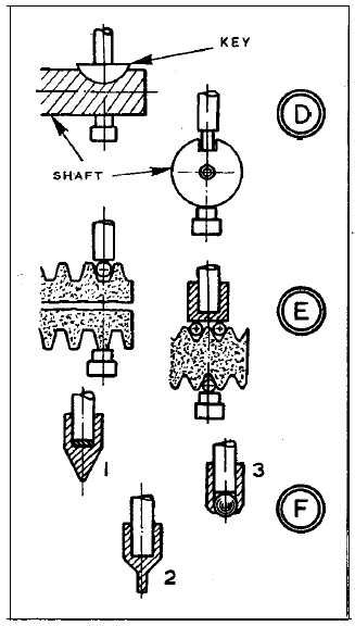
Checking diameters over widely-spaced threads causes difficulty which can be overcome by providing the micrometer spindle with a pad. This is useful, also, when verifying V-threads, as at E (right), by the standard method employing three wires. A gauge which may be to hand will supply the basic reading, or it can be taken from a good specimen of a bolt or screw of similar pitch and profile. With suitable ends on the micrometer spindle, V-shapes and narrow slots can be checked. Examples are as at F (1) and (2), machined in silver steel, hardened and tempered, to place on the spindle with a small chamfered flat disc or washer inside if necessary. A ball end, however, merely requires a steel ball to be soldered or peened in a brass sleeve as shown in F(3).
BEARINGS are the means by which shafts are located, enabled to carry loads and transmit power. All machines necessarily employ them and all engineers must design, construction, lubrication, adjustment, etc. Every bearing must perform one of two functions, or a combination of both: (1) carry radial loads, as a journal bearing; (2) take end loads, as a thrust bearing; (3) take both journal and thrust loads. In some applications, usually of a heavy nature, where both kinds of loads are en countered, a bearing of each type (1 and 2) are fitted, though certain types of bearing combine the functions naturally. There are the plain conical and taper types, cup-and-cone ball bearings, standard journal ball bearings (1/3 of journal load as thrust) and taper roller bearings.
Type Of Bearings
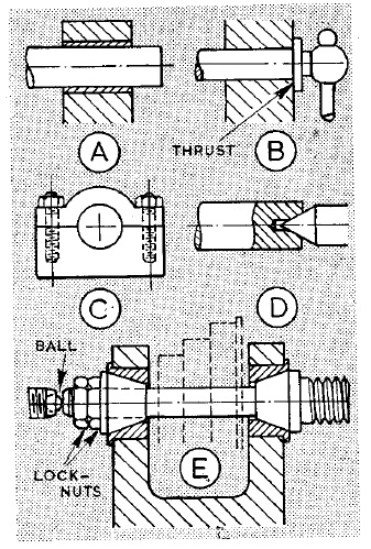
In some instances, where speed of rotation is secondary, no special provision is necessary to take quite heavy thrusts other than a flange on the shaft. The screw of a vice B is a common example. The halved (split-and bolted) bearing, C, whether provided with brasses or a white-metal lining, admits of initial fitting and later adjustment to accommodate wear. In this connection, there may be shims in the joint (steel or brass foil in thicknesses from 0.0015 in. upwards), removal of one or more of which closes the halves to reduce running clearance.
Common Type Of Ball Bearing
Conical Bearings
Between centre turning on a lathe furnishes the most common example of a conical bearing, D, though the same type is used on older lathes for treadle and countershaft bearings. Here the bearing is a hard pad in the end of the shaft, and the pointed adjusting screw is hardened too and fitted with a lock-nut. More substantial bearings of this type are used for the spindles of older and precision lathes E. Locknuts admit of regulating the adjustment for the spindle to turn freely without shake. Solid spindles can have a single ball thrust, though hollow spindles require a thrust in the form of a ring with a number of balls. A separate thrust is essential with this type of bearing for lathe use to prevent seizing.
A Selection of Typical Plain Bearings
Ball Bearings
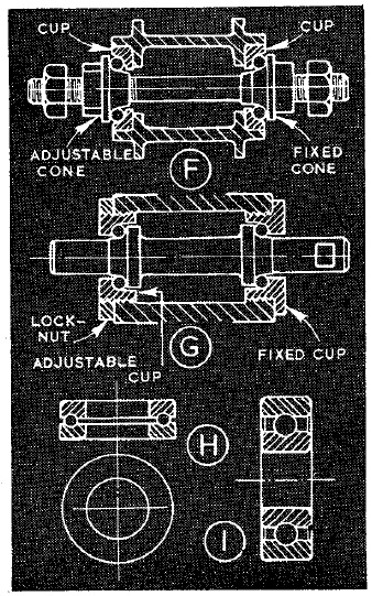
Ball (and roller) bearings possess an advantage over plain types in that rolling is substituted for sliding action-reducing friction and obviating the tendency to seize present on occasion. Disadvantages are all parts of the bearing must be hard and point or line contact involves heavy unit loading. Chipping or scarring of running members can occur. Such bearings, however can carry both journal and thrust loads where neither is too heavy. Common examples are cycle wheel bearings F, and bottom bracket bearings G. On wheel bearings, the cups are pressed in the hubs, one cone is fixed on the spindle and the other adjustable. On bottom bracket bearings, the cones are formed on the spindle, one cup is fixed, and the other adjustable-held by a locknut. Cups are filled with balls, (avoid wedging) and grease to hold them is essential for assembly. Complete new sets of balls must be used, not a mixture of old and new, as old may be undersize. Cycle head races furnish examples of thrust types H, these being adjustable from the top-held by a locknut. The typical ball bearing or race which cannot be dismantled is shown at I. This consists of inner and outer members and a ring of balls located in a cage. A wide range of standard sizes provides for many applications. Outside diameters, bores and widths are held to close dimensions, and housings and shafts are made to light push or driving fits, to obviate rotation other than in the bearing itself.
NUMBEROUS bending and forming operations can be performed in the vice with a hammer and simple mandrels and formers. From round rod can be made hooks, eyes, special staples, chain links; flat sheet or strip serves for light-section angles, channels, boxes and endplates. Small diameters and thin sections can be worked cold but for manipulating large sections using mild steel, a concentrated form of heating is desirable – such as a welding torch – which brings the metal to bright red heat.
Bending And Forming
Forming an Eye
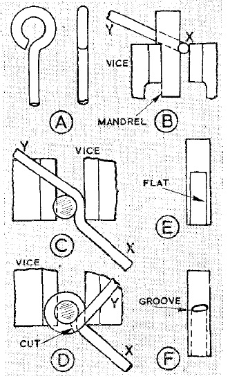
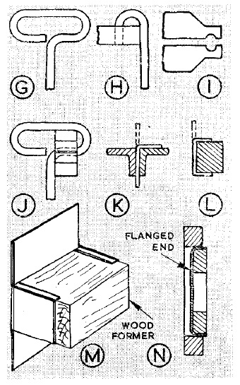
From wire, an eye can be turned on a piece of rod A using round-nosed pliers, but diameters of about 1/8 in. or over require the assistance of the vice. A mandrel from a piece of mild steel rod is then utilized; it is gripped in the vice with the rod B. It is convenient for the mandrel to be provided with a flat one side, filed for the vice jaw to grip; on the opposite side there can be a shallow groove at an angle to locate the rod to be used for the eye. This groove can be cut with a small round file. At the second stage of the work C, the end of the rod X is pulled against the edge of the vice to form the neck; the end Y is then carried round the mandrel to form the eye, as at D. Removed from the vice, the rod is tapped down the mandrel, the surplus cut off and the eye straightened by squeezing in the vice. E and F show the flat and the groove on the mandrel, while these may not be absolutely necessary, they do prevent movement while working. If produced cold, the eye will spring open slightly when pressure is released on the end of the rod Y. Consequently, a mandrel somewhat smaller than the finished inside diameter of the eye is required. At red heat, however, close-fitting eyes can be produced from mild steel rod.
How To Bend And Form
Links and Tee Handles
Chain links and tee handles G can be turned using simple holders. For the first stage H, a hole can be drilled through a piece of bar to take the rod, the end of the hole radiused if necessary. For the second stage, a split holder Z can be made by drilling at the joint of two pieces of bar. Cut to form jaws, they can be gripped about the rod for the second turn of a chain link and utilized as at J for the third turn forming a tee handle.
Channels and Flanges
Short angle lengths in strip metal can be hammered over the vice jaws but for long lengths the strip should be held between two lengths of angle iron K, gripped one end in the vice and the other fixed with a clamp. When an angle is formed, a channel L can be produced over a suitable section piece of bar. For turning thin, ductile sheet metal and strip, hardwood formers of oak or beech should be made to the inside dimensions required, as for the metal box at M. A piece of bar should be clamped on the opposite side of the sheet metal, level with the block where the corner is to be turned- this prevents buckling as the metal is turned over. Round flanged ends, as for small boilers, can be formed from copper discs held between two suitable large washers N and squeezed in a powerful vice. The discs should be annealed before hand; forming can be assisted part of the way through the operation by hammering over the smaller of the washers.
While it is often possible to drill holes over-depth from the tailstock, then face the material to length for accuracy, there are occasions when it is desirable or necessary for the drilling itself to be accurately performed. This is true also of counterboring and cutting angular seatings for which fine control of axial movement is essential. For ordinary work, there are various ways and means of exercising depth control. A pencil mark can be put on the drill, or a nick made on it with the corner of a grinding wheel. The extension of the tailstock barrel can be measured – from the end or from a scribed line or centre punch dot or inside calipers or dividers can be used from the tailstock to a mark on the barrel. These suffice for the occasional job on which better than usual accuracy is required, though for a succession of such jobs, it is a convenience for the means of control to be built into the tailstock in the form of a graduated barrel or a micrometer collar. Then not only is there control for precision work, but for ordinary work there is a check on progress with control over depth clearance, so that bar stock is not wasted in facing out unwanted holes in subsequent use. A graduated barrel for a tailstock can be arranged as at A, with spacing of graduations to choice, 1/32 in. being a normal minimum. Reading should be at a pointer rather than at the end of the tailstock, as the advance to a particular graduation can be seen, and there is no temptation to go beyond to be certain of not under-drilling. Such a pointer can be cut from sheet material, bent, drilled and fixed by screws to the tailstock.
How To Do Tailstock Feed Control
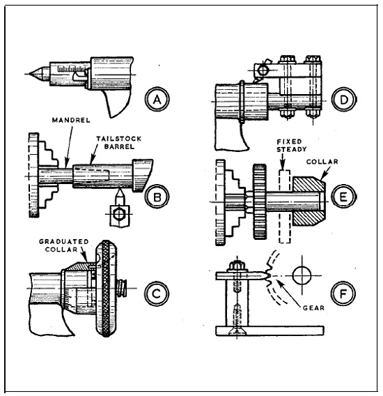
On a screwcutting lathe, the tailstock barrel can be graduated with a set-up as at B. Holding a piece of rod in the chuck, it is machined from the topslide to the taper in the tailstock barrel to form a mandrel on which the barrel can be mounted, leaving clearance from the chuck jaws to work the vee-tool. The handle and key are removed and the barrel allowed to turn in the tailstock body. To mark the base line, the vee-tool is mounted sideways and drawn along the barrel by saddle feed. Then to cut the graduations, with the tool in the normal attitude, the lathe is set to the required thread (say, 32 t.p.i.), and the chuck turned by hand, the tool being fed in at the line and drawn out after a given rotational movement.
A set-up as at D admits of machining the outside of the boss on the tailstock, using a bar through it. Driven from the chuck, this can be flattened at the end for bolting on blocks for the tool, which can be lossened and tapped down for depth of cut. Feed follows from lightly clamping the tailstock to the bed and moving it along with the saddle. The collar can be turned and bored from bar stock or a casting and set up for graduating as at E. For this, its bore can be a force fit on the mandrel which mounts the change gear and is supported by the fixed steady. Later it can be bored to fit the tailstock. Indexing of the gear can be done as at F with a bar bolted to the lathe bed, and a sliding jaw in the teeth of the gear.
